The SuperRT Tools
December 23, 2020
Update 31th May 2021: The source code for SuperRT has now been released.
One thing I learnt very quickly when I started looking at FPGA design was that debugging is hard. Simulation tools exist but from what I’ve seen they are slow, don’t replicate all the quirks of hardware, and for situations like this where interfacing to external devices is an integral part of the design don’t seem to be a good option - to be honest, I gave up pretty quickly on getting anything meaningful out of them and stuck to testing solely on the hardware itself (I fully expect that a large part of this is down to my not really understanding how they are supposed to be used, though - remember that this is my first FPGA project ever and weigh my opinions accordingly!).
Despite having just been rather dismissive of simulators, a massive shout-out is due to 8bitworkshop for “Designing Video Game Hardware in Verilog” (see their site here), whose book not only provides a very accessible tour around the basics of Verilog and how it can be used to build actual gaming hardware, but also has a superb on-line simulator that is very well tailored to videogame-type projects. The very, very first version of the SuperRT tracing code (which mainly just drew an unshaded circle!) was built using this, and had it not existed I would probably have given up long before ever getting to grips with the extra complexities of Quartus and real hardware.
Testing directly on hardware is all well and good, but it also presents its fair share of problems - you more-or-less have to build debugging tools yourself (in the case of SuperRT, this ended up being primarily a debug interface that outputs to HDMI - as seen below - displaying the contents of the internal framebuffer and a bunch of 64-bit debug registers on the screen), and even then the amount of data you can sensibly extract (without building serial interfaces or other cleverness) is limited. Furthermore, the modify-build-test cycle is slow - even on a relatively powerful PC, synthesizing the SuperRT design takes about 40 minutes if all three cores are enabled.
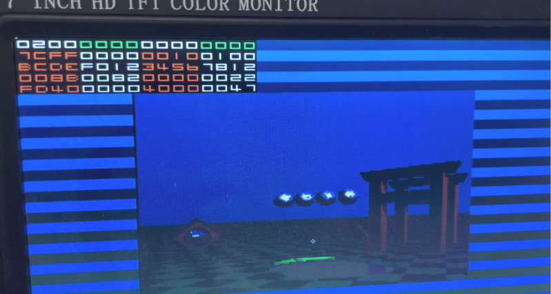
You’d be amazed how many videos I have on my phone that are just 120fps recordings of the debug screen I took so I could scrub through and see values that were changing too fast to read normally! (also, any similarly to the look of a ZX Spectrum loading from tape is entirely accidental)
To combat this, I realised very early in the process that it would be much more efficient to prototype the algorithms separately from the implementation - in this case, by writing a C# application that implements the functionality of the SRT chip (in a manner as close a possible to the actual hardware), thus enabling me to debug that in a reasonably pleasant and efficient environment before moving the code into Verilog.
Having come into FPGA design from a software development perspective, this was one of the most interesting discoveries for me - how critical splitting the validation of algorithmic correctness from implementation correctness was to being able to make progress. Attempting to debug problems with both simultaneously (especially when “exciting” issues such as timing problems and metastability enter the mix!) was exceptionally painful.
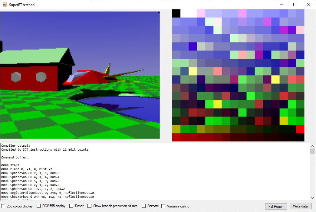
The end result was something of an all-purpose tool, which looks like this:
On the left is the scene view, rendered using the same process as on hardware. This is interactive, so you can move around in realtime using the keyboard. On the right is the palette - SRT uses a fixed 256-colour palette which needs to be generated ahead of time, and as I lack any of the artistic talent that would be necessary to do that by hand it made sense to have the PC build that automatically. The “Pal regen” button renders the scene from a large number of viewpoints and angles, and then generates an optimised palette to represent all those images as best it can.
An interesting fact here - the PC palette generator never moves the sun position, so the palette is optimised for the default lighting, and thus at the moment the colour reproduction quality drops a little when the sun is moved.
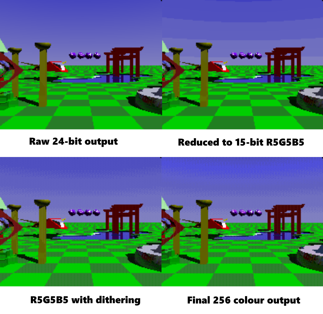
This gives us a chance to see how the palletisation process affects the image, as you can see here, with the original 24-bit internal image data, the 15-bit version (with and without dither), and then the final 8-bit output shown:
At the bottom of the window is the debug display - this shows a disassembly of the current command buffer, and also trace output from the execution engine. By clicking on a pixel in the rendered display, it can be selected for tracing and the results will be shown here.
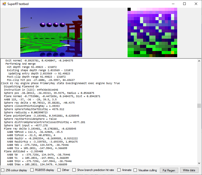
The current pixel is shown surrounded with a black border here (in the sky in the upper-left of the image), and the debug trace output appears below the preview.
The tool also incorporates a scene compiler. This takes a textual representation of the scene and turns it into an SRT command buffer. Initially I built command buffers by hand, which was fine for testing, but as the scene got more complicated this got increasingly unwieldy and so I wrote a compiler to make life easier.
In particular, the compiler has two features which are a big win over hand-assembling scenes. Firstly, it has an object hierarchy, so child nodes are positioned relative to their parents. This means that, for example, the spaceship object can be assembled from a number of individual primitives and then moved/rotated into the desired position as a single unit without having to adjust each part individually.
The SRT chip has an “origin” instruction which can be used to relocate the current coordinate space to allow the SNES to efficiently move a whole model without updating every individual element, but that does not currently have any notion of a hierarchy or rotation component, so the scene compiler offers more flexibility there.
The second big win is that it performs a lot of the calculations needed to turn convenient human-readable scene information into the optimal format for the chip automatically - for example, SRT requires that convex shapes be described as a unison of planes, each expressed as a normal and distance from the origin. The compiler will take a simple list of point describing the vertices of the desired shape and automatically generate that data. The same applies for culling volumes, which are automatically generated by calculating the sizes of the contained objects.
The scene compiler recompiles the command buffer whenever the source scene file is modified on disc, so building a scene has a reasonably fast iteration time as you only have to hit “save” in the text editor and the preview view updates immediately.
The C# implementation of the renderer actually has two complete versions of the core execution engine logic. One is a pipelined cycle-based version that is very close to an exact clone of the Verilog code - well, it might be more accurate to say that the Verilog version is a line-by-line transcription of the C# one. For example, here’s a chunk of the ray-sphere/plane intersection pipeline as it appears in C#:
void RaySphereAndPlane_Cycle8(ExecEngine destData)
{
    bool isSphere = (c8_InstructionWord & 1) == 1; // See Instruction enum for details

    destData.c9_rs_ObjX = c8_rs_ObjX;
    destData.c9_rs_ObjY = c8_rs_ObjY;
    destData.c9_rs_ObjZ = c8_rs_ObjZ;
    destData.c9_rs_distFromSphereCentreToClosestPointSq = c8_rs_distFromSphereCentreToClosestPointSq;
    destData.c9_rs_rayStartInsideSphere = c8_rs_rayStartInsideSphere;
    destData.c9_rs_radiusSq = c8_rs_radiusSq;
    destData.c9_rs_closestPointAlongRay = c8_rs_closestPointAlongRay;

    int rp_denom = FixedMaths.FixedMul16x16(u_RayDirX, c8_rp_normalX) + FixedMaths.FixedMul16x16(u_RayDirY, c8_rp_normalY) + FixedMaths.FixedMul16x16(u_RayDirZ, c8_rp_normalZ);

    // Multiplex the RCP module
    if (isSphere)
    {
        destData.RaySphereAndPlane_RCPModule.rcpIn = c8_rs_ObjRad; // Result becomes available on cycle 13
    }
    else
    {
        destData.RaySphereAndPlane_RCPModule.rcpIn = -rp_denom; // Result becomes available on cycle 13
    }

    x_PipelineTracer?.AppendLine(8, "  Ray dir = " + FixedMaths.FixedToFloat(u_RayDirX) + ", " + FixedMaths.FixedToFloat(u_RayDirY) + ", " + FixedMaths.FixedToFloat(u_RayDirZ));
    x_PipelineTracer?.AppendLine(8, "  Plane normal = " + FixedMaths.FixedToFloat(c8_rp_normalX) + ", " + FixedMaths.FixedToFloat(c8_rp_normalY) + ", " + FixedMaths.FixedToFloat(c8_rp_normalZ));
    x_PipelineTracer?.AppendLine(8, "  Plane denom = " + FixedMaths.FixedToFloat(rp_denom));

    destData.c9_rp_normalX = c8_rp_normalX;
    destData.c9_rp_normalY = c8_rp_normalY;
    destData.c9_rp_normalZ = c8_rp_normalZ;
    destData.c9_rp_dot = c8_rp_dot;
    destData.c9_rp_rayStartInsideVolume = c8_rp_rayStartInsideVolume;
}
…and Verilog:
// Cycle 8
always @(posedge clock) begin
	reg signed [31:0] rp_denom;
	reg isSphere;

	isSphere = c8_instructionWord[0]; // See Instruction enum for details

	c9_rs_objX <= c8_rs_objX;
	c9_rs_objY <= c8_rs_objY;
	c9_rs_objZ <= c8_rs_objZ;
	c9_rs_distFromSphereCentreToClosestPointSq <= c8_rs_distFromSphereCentreToClosestPointSq;
	c9_rs_rayStartInsideSphere <= c8_rs_rayStartInsideSphere;
	c9_rs_radiusSq <= c8_rs_radiusSq;
	c9_rs_closestPointAlongRay <= c8_rs_closestPointAlongRay;

	rp_denom = FixedMul16x16(u_rayDirX, c8_rp_normalX) + FixedMul16x16(u_rayDirY, c8_rp_normalY) + FixedMul16x16(u_rayDirZ, c8_rp_normalZ);

	// Multiplex the RCP module
	c9_rs_rcpIn <= isSphere ? c8_rs_objRad : (-rp_denom); // Result becomes available on cycle 13

	c9_rp_normalX <= c8_rp_normalX;
	c9_rp_normalY <= c8_rp_normalY;
	c9_rp_normalZ <= c8_rp_normalZ;
	c9_rp_dot <= c8_rp_dot;
	c9_rp_rayStartInsideVolume <= c8_rp_rayStartInsideVolume;
end
In case you’re wondering, the odd naming is a convention I came up with to keep track of where things can be safely used within the pipeline -
c8/c9indicates that the registers in question should only be read from cycle 8 or cycle 9, whilstrporrsindicates if they are part of the ray/plane or ray/sphere path.
As you can see, syntax and debugging code aside the two versions are very similar, and the use of destData as a write buffer allows the C# version to emulate the semantics of the <= operator in Verilog, thus making relatively straightforward to take a working algorithm from C# and move it into Verilog without introducing too many errors.
The other execution engine implemented in the C# testbed is a more standard linear procedural one, which uses the same fundamental maths but is a couple of orders of magnitude faster to execute on a standard CPU. I added this mainly to aid scene construction - the cycle-based version is much more useful for debugging, but is so slow that (even using multiple CPU cores) the framerate is in the <1FPS range. The procedural implementation provides a reasonably smooth framerate and makes the scene building process much more user-friendly!
So hopefully that gives you some idea of what the tools I built look like, and the role they’ve played. Everything is a little bit thrown together, but it does the job well enough and enabled me to develop the Verilog side without hitting too many problems along the way.